The only way you can solder wires to those pins is either through your own custom made pcb or you have the hands of a surgeon, and you have a really fine.
40+ Micro Usb To Usb C Wiring Diagram Background. In the design, i use an atmel micro, usb2.0 through a micro usb connector. What would a wiring diagram look like?
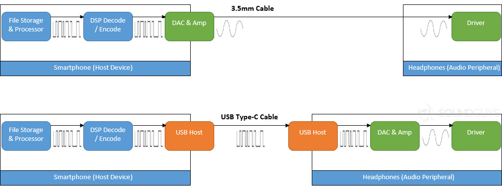
Usb Audio And Usb Type C Headphones Explained from www.soundguys.com
My soldering and drawing skills are not the very best but with the help of. In this video i tried to explain the connection diagram of a micro usb connector. This cable is most commonly used in mobile charger for charging mobile phones and as a usb data cable to connect mobile devices to tranfer files and images between personal computers and phones.
There's 7 solder points on top of the small pcb.
The initial versions of the usb standard specified connectors that were easy to use and that would have acceptable life spans. There's 7 solder points on top of the small pcb. The micro usb type band micro usb type c folders contains documentation i used to make this proyect, it includes the pdfs of the usb spefication of usb type c mid plate dimensions. Is true that the pads itself are not below or above that.